
Product catalogue / 11
PTFE-Lined Valves & Chemical Transfer Connections
Lined isolation valves and chemical transfer interfaces. Confirm full wetted-material compatibility and the exact connection specification.
11 traceable product codesProduct models and configurations
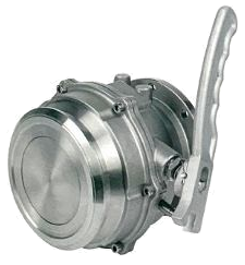 SIMEI FT-CAPI-100
80 mm stainless-steel bottom-loading adaptor valve
Quick-connect bottom-loading and discharge adaptor for the lower side of a tanker, for diesel, petrol, kerosene and other light fuels subject to seal compatibility.
Technical details
80 mm stainless-steel bottom-loading adaptor valve
Quick-connect bottom-loading and discharge adaptor for the lower side of a tanker, for diesel, petrol, kerosene and other light fuels subject to seal compatibility.
Technical detailsMain features
- Mechanical quick-connection structure supports connection and detachment at the bottom-loading system.
- The illustrated valve uses a lever operating mechanism.
- The connection is intended to limit leakage during detachment; confirm the supplied sealing arrangement and test criteria.
Available Configurations
- Quick-connect tanker-side interface.
Technical & Ordering Data
| Nominal size | 80 mm nominal designation |
|---|---|
| Material | Stainless steel; grade to confirm |
| Connection reference | API RP1004 dimensional interface reference; verify the mating interface and supporting documentation |
| Operation | Mechanical lever |
| Working pressure | Confirm before quotation |
| Temperature / seals | Confirm before quotation |
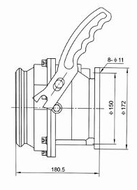
| Drawing dimensions | 180.5 axial reference; Ø150 / Ø172 flange references; 8 × Ø11 mounting holes (mm) |
Dimensions & Construction (1)
Drawings are selection references. Confirm dimensions, tolerances and interfaces against the approved drawing before manufacture.
Confirm Before Order
- Confirm the mating loading coupler, pressure rating, seal material, temperature range and compatibility with the actual cargo.
- Any API dimensional-conformity requirement must be agreed and verified for the supplied SIMEI configuration.
Engineering Note
Agree and verify the interface dimensions and any required compliance documentation for the supplied configuration.
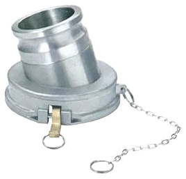 SIMEI FT-CGC-100
Stainless-steel gravity-drop coupler
Gravity-discharge connection accessory with a hose outlet and quick-coupling base.
Technical details
Stainless-steel gravity-drop coupler
Gravity-discharge connection accessory with a hose outlet and quick-coupling base.
Technical detailsMain features
- The photograph shows a hose-spigot outlet, retaining latch and tether chain.
Available Configurations
- Illustrated coupler and tether chain.
Technical & Ordering Data
| Material | Stainless steel; exact grade to confirm |
|---|---|
| Connection | Quick-coupling base with hose-spigot outlet; mating size to confirm |
| Nominal size / pressure | Confirm before quotation |
| Seals / temperature | Confirm before quotation |
Confirm Before Order
- Confirm nominal size, wetted material grade, seals, pressure rating, temperature limits and mating dimensions before quotation.
- Confirm compatibility with the selected tanker adaptor and discharge hose.
Engineering Note
Approve the mating-interface drawing and complete operating specification before quotation.
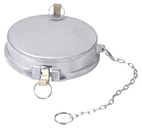 SIMEI FT-CGC-110
Stainless-steel transfer dust cap
Protective closure for a tanker transfer-adaptor interface when the connection is unused.
Technical details
Stainless-steel transfer dust cap
Protective closure for a tanker transfer-adaptor interface when the connection is unused.
Technical detailsMain features
- The photograph shows a circular cap with retaining latch and tether chain.
Available Configurations
- Illustrated cap with tether chain.
Technical & Ordering Data
| Material | Stainless steel; exact grade to confirm |
|---|---|
| Connection | Quick-fit protective cap; mating size to confirm |
| Nominal size / pressure | Confirm before quotation |
| Seals / temperature | Confirm before quotation |
Confirm Before Order
- Confirm nominal size, wetted material grade, seals, pressure rating, temperature limits and mating dimensions before quotation.
- Confirm the mating adaptor and whether a pressure-retaining closure is required.
Engineering Note
Confirm separately if the closure must retain pressure.
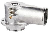 SIMEI FT-CVV-100
80 mm stainless-steel vapour vent valve
Tank-top vapour flow control during tanker loading and unloading; the outlet connects by rubber hose to vapour-recovery pipework.
Technical details
80 mm stainless-steel vapour vent valve
Tank-top vapour flow control during tanker loading and unloading; the outlet connects by rubber hose to vapour-recovery pipework.
Technical detailsMain features
- Installs on a manhole cover or directly at the top of the tank.
- Controls vapour entering or leaving the tank during loading and unloading.
- Provides the tank-side valve connection for a vapour-recovery system.
Available Configurations
- Hose connection to the vapour-recovery line.
Technical & Ordering Data
| Nominal diameter | 80 mm / 3 inch |
|---|---|
| Nominal pressure | 0.4 MPa |
| Main material | Stainless steel; grade to confirm |
| Installation / opening | Pneumatic, specified configuration |
| Temperature range | −40 to +150°C |
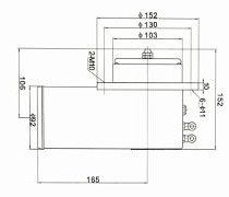
| Drawing diameters | Ø152 / Ø130 / Ø103 top references; Ø92 outlet (mm) |
| Drawing dimensions | 165 horizontal reference; 105 centre height; 152 total-height reference; 10 flange thickness (mm) |
| Drawing ports / mounting | 2 × M10; 6 × Ø11 mounting holes |
Dimensions & Construction (1)
Drawings are selection references. Confirm dimensions, tolerances and interfaces against the approved drawing before manufacture.
Confirm Before Order
- Confirm pneumatic supply pressure, seal material, stainless-steel grade and chemical compatibility.
- Approve the controlled connection drawing before ordering.
- Pneumatic opening is specified; confirm separately if manual actuation is required.
Engineering Note
Match the tank, hose and vapour-recovery interfaces, and specify the seal and pneumatic circuit.
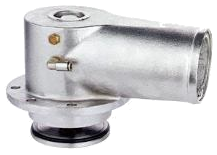 SIMEI FT-CVV-110
80 mm stainless-steel coaming vent valve
Vapour-pipe venting at the tank top, with a normally open arrangement for vapour entering and leaving the pipework.
Technical details
80 mm stainless-steel coaming vent valve
Vapour-pipe venting at the tank top, with a normally open arrangement for vapour entering and leaving the pipework.
Technical detailsMain features
- Installs on the pipework at the end of the tank top.
- The described outlet points downward at 45 degrees to the horizontal to reduce dust accumulation and entry.
- In its normally open state it permits vapour movement into and out of the pipework.
Available Configurations
- Normally open vent configuration.
Technical & Ordering Data
| Nominal diameter | 80 mm / 3 inch |
|---|---|
| Nominal pressure | 0.4 MPa |
| Main material | Stainless steel; grade to confirm |
| Installation / opening | Pneumatic, specified configuration |
| Temperature range | −20 to +120°C |
| Outlet description | 45-degree downward orientation described; verify against supplied geometry |
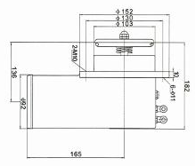
| Drawing diameters | Ø152 / Ø130 / Ø103 top references; Ø92 outlet (mm) |
| Drawing dimensions | 165 horizontal reference; 136 centre-height reference; 182 total-height reference; 10 flange thickness (mm) |
| Drawing ports / mounting | 2 × M10; 6 × Ø11 mounting holes |
Dimensions & Construction (1)
Drawings are selection references. Confirm dimensions, tolerances and interfaces against the approved drawing before manufacture.
Confirm Before Order
- Confirm pneumatic supply pressure, seal material, stainless-steel grade and chemical compatibility.
- Approve the controlled connection drawing before ordering.
- Confirm the required downward outlet angle against the supplied valve geometry.
Engineering Note
Confirm outlet orientation, normal state and pneumatic control function together.
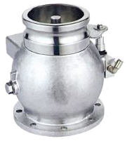 SIMEI FT-CVV-120
80 mm stainless-steel vapour-recovery adaptor valve
Quick connection for vapour transfer near the tanker unloading position, with an interlock for the coaming vent circuit.
Technical details
80 mm stainless-steel vapour-recovery adaptor valve
Quick connection for vapour transfer near the tanker unloading position, with an interlock for the coaming vent circuit.
Technical detailsMain features
- Installs on the lower side of the tank near the unloading point.
- Controls vapour flow entering and leaving the tank.
- The built-in interlock is contacted by the mating coupler and can control the coaming vent valve.
Available Configurations
- Mating-coupler-actuated interlock.
Technical & Ordering Data
| Nominal diameter | 80 mm / 3 inch |
|---|---|
| Nominal pressure | 0.4 MPa |
| Main material | Stainless steel; grade to confirm |
| Installation / opening | Pneumatic, specified configuration |
| Temperature range | −40 to +120°C |
| Connection | Quick-connect adaptor with interlock |
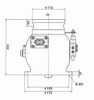
| Drawing diameters | Ø119 coupling reference; Ø150 / Ø172 flange references (mm) |
| Drawing dimensions | 200 vertical reference; 24 coupling-groove reference; 12 flange thickness (mm) |
| Drawing mounting | 6 × Ø11 holes; additional small upper chamfer callout requires confirmation |
Dimensions & Construction (1)
Drawings are selection references. Confirm dimensions, tolerances and interfaces against the approved drawing before manufacture.
Confirm Before Order
- Confirm pneumatic supply pressure, seal material, stainless-steel grade and chemical compatibility.
- Approve the controlled connection drawing before ordering.
- Confirm the mating coupler, interlock stroke and the complete pneumatic vent-control circuit.
- Confirm the complete coupling-profile and chamfer dimensions.
Engineering Note
The interlock is a system interface: compatibility with the mating coupler and connected vent valve must be established before supply.
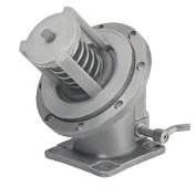 SIMEI FT-PTFE-100
80 mm manual PTFE-lined stainless bottom valve
PTFE-lined isolation for chemical-tanker discharge and transfer of corrosive or toxic media; select the complete wetted construction for the intended chemical.
Technical details
80 mm manual PTFE-lined stainless bottom valve
PTFE-lined isolation for chemical-tanker discharge and transfer of corrosive or toxic media; select the complete wetted construction for the intended chemical.
Technical detailsMain features
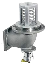
- PTFE lining covers the valve body interior, spring pressure cover and valve disc.
- Stainless-steel construction provides mechanical support to the corrosion-resistant PTFE wetted lining.
- The 45-degree body installs at the tanker bottom and is operated manually.
- A manual hold-open device prevents automatic closure after it has been engaged.
Available Configurations
- 45-degree bottom-outlet arrangement.
- PTFE-lined spring pressure cover and disc.
- PTFE-lined valve-body bore.
Technical & Ordering Data
| Nominal size | 80 mm; family sizes 3 in / 4 in |
|---|---|
| Nominal pressure | 0.6 MPa (family data) |
| Body / wetted lining | Stainless steel / PTFE; exact steel grade and PTFE specification to confirm |
| Installation | Flange connection |
| Temperature range | −40 to +150°C (family data; verify for the chemical, seals and configuration) |
| Operation | Manual, with hold-open device |
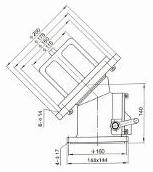
| Drawing reference dimensions | Height reference 140; outlet face 146 × 146; bore reference Ø100; outlet holes 4 × Ø17; tank-flange holes 8 × Ø14 (mm; confirm drawing interpretation) |

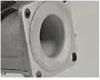
Dimensions & Construction (1)
Drawings are selection references. Confirm dimensions, tolerances and interfaces against the approved drawing before manufacture.
Confirm Before Order
- Confirm chemical compatibility and the exact PTFE-lined wetted surfaces for the supplied configuration.
- Obtain a controlled dimensional drawing before approving flange drilling.
- Confirm the selected manual or pneumatic actuation and any opening-pressure requirement.
- Confirm the complete tank-flange diameters and drilling before quotation.
Engineering Note
Verify the assembled valve, lining, seals and accessories for the specified medium and duty; family data require confirmation for the selected configuration.
 SIMEI FT-PTFE-110
100 mm pneumatic PTFE-lined stainless bottom valve
PTFE-lined isolation for chemical-tanker discharge and transfer of corrosive or toxic media; select the complete wetted construction for the intended chemical.
Technical details
100 mm pneumatic PTFE-lined stainless bottom valve
PTFE-lined isolation for chemical-tanker discharge and transfer of corrosive or toxic media; select the complete wetted construction for the intended chemical.
Technical detailsMain features
- PTFE lining covers the valve body interior, spring pressure cover and valve disc.
- Stainless-steel construction provides mechanical support to the corrosion-resistant PTFE wetted lining.
- The cylinder assembly can be removed for maintenance or replacement.
- An emergency opening provision allows the valve to be opened manually in an emergency.
Available Configurations
- Fusible element illustrated; release temperature is not supplied.
- Replaceable pneumatic cylinder assembly.
- PTFE-lined spring cover, disc and valve body.
Technical & Ordering Data
| Nominal size | 100 mm; family sizes 3 in / 4 in |
|---|---|
| Nominal pressure | 0.6 MPa (family data) |
| Body / wetted lining | Stainless steel / PTFE; exact steel grade and PTFE specification to confirm |
| Installation | Flange connection |
| Temperature range | −40 to +150°C (family data; verify for the chemical, seals and configuration) |
| Operation | Pneumatic cylinder with emergency manual opening provision |
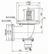
| Tank flange drawing | Ø220 outer / Ø190 reference; 8 × Ø14 equally spaced holes; 16 thickness (mm) |
| Outlet drawing | 165 × 165 flange; Ø170 and Ø135 references; 4 × Ø17 equally spaced holes (mm; reference interpretation requires confirmation) |
| Other drawing references | 150 upper height; 105 centre offset; 152 horizontal centre distance (mm) |


Dimensions & Construction (1)
Drawings are selection references. Confirm dimensions, tolerances and interfaces against the approved drawing before manufacture.
Confirm Before Order
- Confirm chemical compatibility and the exact PTFE-lined wetted surfaces for the supplied configuration.
- Obtain a controlled dimensional drawing before approving flange drilling.
- Confirm the selected manual or pneumatic actuation and any opening-pressure requirement.
- Confirm the emergency-opening procedure, air supply pressure and fusible-element release temperature.
Engineering Note
Verify the assembled valve, lining, seals and accessories for the specified medium and duty; family data require confirmation for the selected configuration.
 SIMEI FT-PTFE-120
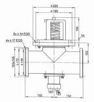
100 mm three-way pneumatic PTFE-lined bottom valve
PTFE-lined isolation for chemical-tanker discharge and transfer of corrosive or toxic media; select the complete wetted construction for the intended chemical.
Technical details
100 mm three-way pneumatic PTFE-lined bottom valve
PTFE-lined isolation for chemical-tanker discharge and transfer of corrosive or toxic media; select the complete wetted construction for the intended chemical.
Technical detailsMain features
- PTFE lining covers the valve body interior, spring pressure cover and valve disc.
- Stainless-steel construction provides mechanical support to the corrosion-resistant PTFE wetted lining.
- The removable cylinder assembly supports maintenance and replacement.
- An emergency opening provision allows manual opening in an emergency.
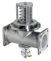
- The T-type body connects side pipelines directly for split-flow arrangements.
Available Configurations
- Two opposed side outlets in a T-type body.
- Fusible element illustrated; release temperature is not supplied.
- Replaceable pneumatic cylinder assembly.
- PTFE-lined spring cover, disc and valve body.
Technical & Ordering Data
| Nominal size | 100 mm; family sizes 3 in / 4 in |
|---|---|
| Nominal pressure | 0.6 MPa (family data) |
| Body / wetted lining | Stainless steel / PTFE; exact steel grade and PTFE specification to confirm |
| Installation | Flange connection |
| Temperature range | −40 to +150°C (family data; verify for the chemical, seals and configuration) |
| Operation | Pneumatic cylinder with emergency manual opening provision |
| Tank flange drawing | Ø220 outer / Ø190 reference; 8 × Ø14 equally spaced holes; 16 thickness (mm) |
| Side outlet drawing | 165 × 165 flange; Ø170 and Ø138 references; 4 × Ø17 equally spaced holes (mm; verify Ø138 against the controlled drawing) |
| Other drawing references | 150 upper height; 150 vertical centre reference; 152 centre-to-face on each side (mm) |


Dimensions & Construction (1)
Drawings are selection references. Confirm dimensions, tolerances and interfaces against the approved drawing before manufacture.
Confirm Before Order
- Confirm chemical compatibility and the exact PTFE-lined wetted surfaces for the supplied configuration.
- Obtain a controlled dimensional drawing before approving flange drilling.
- Confirm the selected manual or pneumatic actuation and any opening-pressure requirement.
- Confirm the side-flange inner reference dimension before mating-pipe design.
- Confirm air supply pressure, manual emergency-opening procedure and fusible-element release temperature.
Engineering Note
Verify the assembled valve, lining, seals and accessories for the specified medium and duty; family data require confirmation for the selected configuration.
 SIMEI FT-PTFE-130
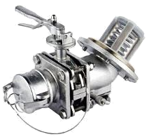
80 mm PTFE-lined bottom valve with butterfly outlet
PTFE-lined isolation for chemical-tanker discharge and transfer of corrosive or toxic media; select the complete wetted construction for the intended chemical.
Technical details
80 mm PTFE-lined bottom valve with butterfly outlet
PTFE-lined isolation for chemical-tanker discharge and transfer of corrosive or toxic media; select the complete wetted construction for the intended chemical.
Technical detailsMain features
- PTFE lining covers the valve body interior, spring pressure cover and valve disc.
- Stainless-steel construction provides mechanical support to the corrosion-resistant PTFE wetted lining.
- A manual hold-open device prevents automatic closure after engagement.
- The PTFE-lined bottom valve, butterfly outlet and dust cap form the illustrated three-sealing arrangement.
Available Configurations
- PTFE-lined butterfly outlet.
- PTFE-lined male flange.
- PTFE-lined spring pressure cover and disc.
- PTFE-lined valve body.
- PTFE-lined dust cap shown in the assembled photograph.
Technical & Ordering Data
| Nominal size | 80 mm; family sizes 3 in / 4 in |
|---|---|
| Nominal pressure | 0.6 MPa (family data) |
| Body / wetted lining | Stainless steel / PTFE; exact steel grade and PTFE specification to confirm |
| Installation | Flange connection |
| Temperature range | −40 to +150°C (family data; verify for the chemical, seals and configuration) |
| Operation | Manual hold-open device and lever-operated butterfly valve |
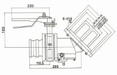
| Drawing reference dimensions | Handle reference 220; height reference 185; horizontal references 110.5 and 280; tank-flange holes 8 × Ø14 (mm) |



Dimensions & Construction (1)
Drawings are selection references. Confirm dimensions, tolerances and interfaces against the approved drawing before manufacture.
Confirm Before Order
- Confirm chemical compatibility and the exact PTFE-lined wetted surfaces for the supplied configuration.
- Obtain a controlled dimensional drawing before approving flange drilling.
- Confirm the selected manual or pneumatic actuation and any opening-pressure requirement.
- Confirm the complete tank-flange diameters and drilling before quotation.
Engineering Note
Verify the assembled valve, lining, seals and accessories for the specified medium and duty; family data require confirmation for the selected configuration.
 SIMEI FT-PTFE-140
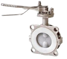
80 mm in-line PTFE-lined valve
Independent pipeline isolation for corrosive or toxic media using a lever-operated PTFE-lined valve.
Technical details
80 mm in-line PTFE-lined valve
Independent pipeline isolation for corrosive or toxic media using a lever-operated PTFE-lined valve.
Technical detailsMain features
- PTFE lining covers the valve body interior, spring pressure cover and valve disc.
- Stainless-steel construction provides mechanical support to the corrosion-resistant PTFE wetted lining.
- The valve can be installed independently in a pipeline to open or close the medium flow.
Available Configurations
- Independent pipeline installation.
Technical & Ordering Data
| Nominal size | 80 mm; family sizes 3 in / 4 in |
|---|---|
| Nominal pressure | 0.6 MPa (family data) |
| Body / wetted lining | Stainless steel / PTFE; exact steel grade and PTFE specification to confirm |
| Installation | Flange connection |
| Temperature range | −40 to +150°C (family data; verify for the chemical, seals and configuration) |
| Operation | Manual lever |
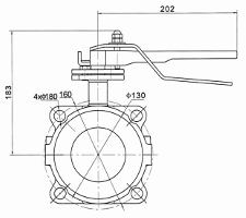
| Drawing reference dimensions | Handle reference 202; height-to-centre reference 183; Ø160 and Ø130 references; 4 × Ø18 mounting holes (mm) |
Dimensions & Construction (1)
Drawings are selection references. Confirm dimensions, tolerances and interfaces against the approved drawing before manufacture.
Confirm Before Order
- Confirm chemical compatibility and the exact PTFE-lined wetted surfaces for the supplied configuration.
- Obtain a controlled dimensional drawing before approving flange drilling.
- Confirm the selected manual or pneumatic actuation and any opening-pressure requirement.
Engineering Note
Verify the assembled valve, lining, seals and accessories for the specified medium and duty; family data require confirmation for the selected configuration.
SIMEI ENERGY
Selection and ordering
Send the SIMEI code, quantity, transported medium, operating conditions and mating drawing. Confirm materials, seals, interfaces and operating requirements before ordering.