
Product catalogue / 01
Fuel Tanker Manhole Covers & P/V Vents
Top access, emergency pressure relief and normal tank breathing. Select the cover, vent and accessory interfaces together.
20 traceable product codesProduct models and configurations
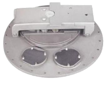 SIMEI FT-MH-100
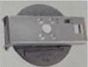
460 mm cast-plate tanker manhole cover
Provides top access, automatic emergency pressure release and pressure/vacuum balancing for a fuel tanker; the illustrated accessory arrangement supports the specified tanker installation.
Technical details
460 mm cast-plate tanker manhole cover
Provides top access, automatic emergency pressure release and pressure/vacuum balancing for a fuel tanker; the illustrated accessory arrangement supports the specified tanker installation.
Technical detailsMain features
- Top-mounted access cover for tanks carrying gasoline, diesel, kerosene and other light fuels.
- An emergency exhaust mechanism automatically releases internal pressure when tank temperature or pressure rises.
- An internal pressure/vacuum vent admits or releases air to balance tank pressure.
- The secondary opening arrangement releases residual pressure before access; confirm the supplied latch configuration.
- Accessory openings can accommodate level sensing, vapour venting and dip-tube fittings where provided.
- Both plates are cast and surface treated by oxidation.
- Compact construction; the source describes relatively low manufacturing cost.
- Two accessory openings accept an optical sensor, dip tube or external pressure/vacuum vent.
Available Configurations
- Single or double pressure/vacuum vent arrangement as required.
- Optical sensor, dip tube or external pressure/vacuum vent at the two accessory openings.
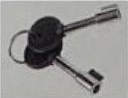
- Key, secondary opening device and emergency exhaust assembly are illustrated.
Technical & Ordering Data
| Nominal size | 460 mm nominal cover variant |
|---|---|
| Body / plate material | Cast main plate and small plate; aluminium alloy indicated by the family table, exact grade to confirm |
| Connection / operation | Top-mounted flanged cover; manual access opening with pressure-relief provisions |
| Emergency opening pressure | 21–35 kPa (catalogue family value; confirm setting for supplied assembly) |
| Maximum emergency airflow | 7,000 m³/h at 34 kPa (catalogue family value) |
| Temperature | −40 to +50 °C (catalogue family value) |
| Family nominal size reference | 20 in in the family table; individual variant dimensions are listed separately |
| Seal material | Confirm before quotation |
| Working pressure | Rated working pressure not stated; emergency opening pressure is a separate parameter |
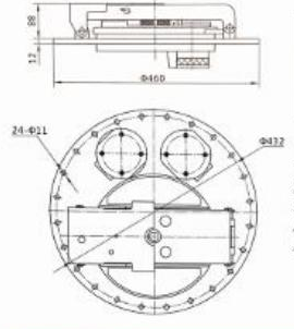
| Drawing outer diameter | Ø460 mm |
| Drawing diameter callout | Ø437 mm; confirm its mounting function against the approved drawing |
| Drawing holes | 24 × Ø11 mm |
| Drawing vertical callouts | 88 mm above plate; plate callout 12 mm |
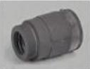
Dimensions & Construction (1)
Drawings are selection references. Confirm dimensions, tolerances and interfaces against the approved drawing before manufacture.
Confirm Before Order
- Confirm seal compound and compatibility with the actual cargo.
- Confirm the emergency relief setting and flow rating for the supplied assembly.
- Confirm the drawing revision, mating tank opening and mounting arrangement; the family table gives 20 in across several variant sizes.
- Confirm which vents, sensor, dip tube, key, latch, hoop and base are included rather than optional.
Engineering Note
Values are transcribed from the supplied catalogue and are selection references, not a SIMEI test certificate or manufacturing approval. The photograph is the exact source model photograph; accessory illustrations may be shared where the same original detail recurs.
 SIMEI FT-MH-110
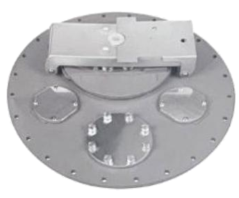
560 mm cast-plate tanker manhole cover
Provides top access, automatic emergency pressure release and pressure/vacuum balancing for a fuel tanker; the illustrated accessory arrangement supports the specified tanker installation.
Technical details
560 mm cast-plate tanker manhole cover
Provides top access, automatic emergency pressure release and pressure/vacuum balancing for a fuel tanker; the illustrated accessory arrangement supports the specified tanker installation.
Technical detailsMain features
- Top-mounted access cover for tanks carrying gasoline, diesel, kerosene and other light fuels.
- An emergency exhaust mechanism automatically releases internal pressure when tank temperature or pressure rises.
- An internal pressure/vacuum vent admits or releases air to balance tank pressure.
- The secondary opening arrangement releases residual pressure before access; confirm the supplied latch configuration.
- Accessory openings can accommodate level sensing, vapour venting and dip-tube fittings where provided.
- Both plates are cast and surface treated by oxidation.
- Compact construction; the source describes relatively low manufacturing cost.
- Three accessory openings accept an optical sensor, dip tube or external pressure/vacuum vent.
Available Configurations
- Single or double pressure/vacuum vent arrangement as required.
- Optical sensor, dip tube or external pressure/vacuum vent at the three accessory openings.
- Key, secondary opening device and emergency exhaust assembly are illustrated.
Technical & Ordering Data
| Nominal size | 560 mm nominal cover variant |
|---|---|
| Body / plate material | Cast main plate and small plate; aluminium alloy indicated by the family table, exact grade to confirm |
| Connection / operation | Top-mounted flanged cover; manual access opening with pressure-relief provisions |
| Emergency opening pressure | 21–35 kPa (catalogue family value; confirm setting for supplied assembly) |
| Maximum emergency airflow | 7,000 m³/h at 34 kPa (catalogue family value) |
| Temperature | −40 to +50 °C (catalogue family value) |
| Family nominal size reference | 20 in in the family table; individual variant dimensions are listed separately |
| Seal material | Confirm before quotation |
| Working pressure | Rated working pressure not stated; emergency opening pressure is a separate parameter |
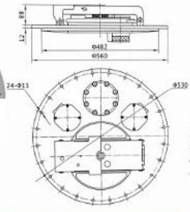
| Drawing outer diameter | Ø560 mm |
| Drawing inner diameter callout | Ø482 mm; confirm functional meaning |
| Drawing mounting diameter callout | Ø530 mm; confirm against approved mating drawing |
| Drawing holes | 24 × Ø11 mm |
| Drawing vertical callouts | 88 mm above plate; plate callout 12 mm |
Dimensions & Construction (1)
Drawings are selection references. Confirm dimensions, tolerances and interfaces against the approved drawing before manufacture.
Confirm Before Order
- Confirm seal compound and compatibility with the actual cargo.
- Confirm the emergency relief setting and flow rating for the supplied assembly.
- Confirm the drawing revision, mating tank opening and mounting arrangement; the family table gives 20 in across several variant sizes.
- Confirm which vents, sensor, dip tube, key, latch, hoop and base are included rather than optional.
Engineering Note
Values are transcribed from the supplied catalogue and are selection references, not a SIMEI test certificate or manufacturing approval. The photograph is the exact source model photograph; accessory illustrations may be shared where the same original detail recurs.
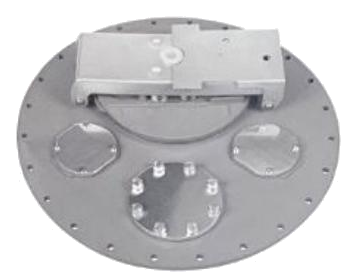 SIMEI FT-MH-120
580 mm cast-plate tanker manhole cover
Provides top access, automatic emergency pressure release and pressure/vacuum balancing for a fuel tanker; the illustrated accessory arrangement supports the specified tanker installation.
Technical details
580 mm cast-plate tanker manhole cover
Provides top access, automatic emergency pressure release and pressure/vacuum balancing for a fuel tanker; the illustrated accessory arrangement supports the specified tanker installation.
Technical detailsMain features
- Top-mounted access cover for tanks carrying gasoline, diesel, kerosene and other light fuels.
- An emergency exhaust mechanism automatically releases internal pressure when tank temperature or pressure rises.
- An internal pressure/vacuum vent admits or releases air to balance tank pressure.
- The secondary opening arrangement releases residual pressure before access; confirm the supplied latch configuration.
- Accessory openings can accommodate level sensing, vapour venting and dip-tube fittings where provided.
- Both plates are cast and surface treated by oxidation.
- Compact construction; the source describes relatively low manufacturing cost.
- Three accessory openings accept an optical sensor, dip tube or external pressure/vacuum vent.
Available Configurations
- Single or double pressure/vacuum vent arrangement as required.
- Optical sensor, dip tube or external pressure/vacuum vent at the three accessory openings.
- Key, secondary opening device and emergency exhaust assembly are illustrated.
Technical & Ordering Data
| Nominal size | 580 mm nominal cover variant |
|---|---|
| Body / plate material | Cast main plate and small plate; aluminium alloy indicated by the family table, exact grade to confirm |
| Connection / operation | Top-mounted flanged cover; manual access opening with pressure-relief provisions |
| Emergency opening pressure | 21–35 kPa (catalogue family value; confirm setting for supplied assembly) |
| Maximum emergency airflow | 7,000 m³/h at 34 kPa (catalogue family value) |
| Temperature | −40 to +50 °C (catalogue family value) |
| Family nominal size reference | 20 in in the family table; individual variant dimensions are listed separately |
| Seal material | Confirm before quotation |
| Working pressure | Rated working pressure not stated; emergency opening pressure is a separate parameter |
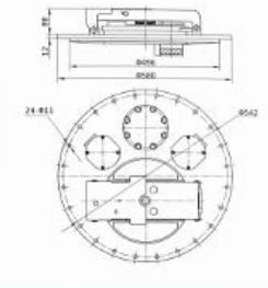
| Drawing outer diameter | Ø580 mm |
| Drawing diameter callout | Ø542 mm; confirm mounting function |
| Drawing holes | 24 × Ø11 mm |
| Drawing vertical callouts | 88 mm and 12 mm; confirm from approved drawing |
Dimensions & Construction (1)
Drawings are selection references. Confirm dimensions, tolerances and interfaces against the approved drawing before manufacture.
Confirm Before Order
- Confirm seal compound and compatibility with the actual cargo.
- Confirm the emergency relief setting and flow rating for the supplied assembly.
- Confirm the drawing revision, mating tank opening and mounting arrangement; the family table gives 20 in across several variant sizes.
- Confirm which vents, sensor, dip tube, key, latch, hoop and base are included rather than optional.
- The inner diameter callout in the elevation view is blurred and is not transcribed.
Engineering Note
Values are transcribed from the supplied catalogue and are selection references, not a SIMEI test certificate or manufacturing approval. The photograph is the exact source model photograph; accessory illustrations may be shared where the same original detail recurs.
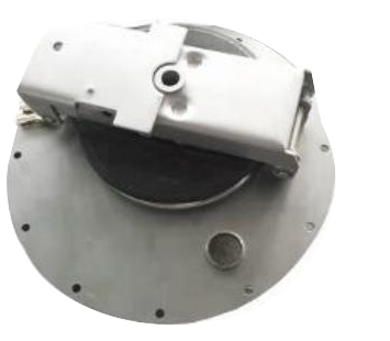 SIMEI FT-MH-130
460 mm pressed-plate tanker manhole cover with dip-tube port
Provides top access, automatic emergency pressure release and pressure/vacuum balancing for a fuel tanker; the illustrated accessory arrangement supports the specified tanker installation.
Technical details
460 mm pressed-plate tanker manhole cover with dip-tube port
Provides top access, automatic emergency pressure release and pressure/vacuum balancing for a fuel tanker; the illustrated accessory arrangement supports the specified tanker installation.
Technical detailsMain features
- Top-mounted access cover for tanks carrying gasoline, diesel, kerosene and other light fuels.
- An emergency exhaust mechanism automatically releases internal pressure when tank temperature or pressure rises.
- An internal pressure/vacuum vent admits or releases air to balance tank pressure.
- The secondary opening arrangement releases residual pressure before access; confirm the supplied latch configuration.
- Accessory openings can accommodate level sensing, vapour venting and dip-tube fittings where provided.
- The main plate is formed from steel sheet.
- Main-plate material and dimensions can be made to the required specification.
- The position and dimensions of the small plate can be customized.
- One blanked accessory opening accepts the FT-AC-120 dip tube.
Available Configurations
- Single or double pressure/vacuum vents as required.
- One dip-tube opening, illustrated with an external fitting.
- Key, secondary opening device and emergency exhaust assembly are illustrated.
Technical & Ordering Data
| Nominal size | 460 mm nominal cover variant |
|---|---|
| Body / plate material | Pressed steel main plate; grade and small-plate material to be confirmed |
| Connection / operation | Top-mounted flanged cover; manual access opening with pressure-relief provisions |
| Emergency opening pressure | 21–35 kPa (catalogue family value; confirm setting for supplied assembly) |
| Maximum emergency airflow | 7,000 m³/h at 34 kPa (catalogue family value) |
| Temperature | −40 to +50 °C (catalogue family value) |
| Family nominal size reference | 20 in in the family table; individual variant dimensions are listed separately |
| Seal material | Confirm before quotation |
| Working pressure | Rated working pressure not stated; emergency opening pressure is a separate parameter |
Dimensions & Construction (1)
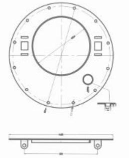
Drawings are selection references. Confirm dimensions, tolerances and interfaces against the approved drawing before manufacture.
Confirm Before Order
- Confirm seal compound and compatibility with the actual cargo.
- Confirm the emergency relief setting and flow rating for the supplied assembly.
- Confirm the drawing revision, mating tank opening and mounting arrangement; the family table gives 20 in across several variant sizes.
- Confirm which vents, sensor, dip tube, key, latch, hoop and base are included rather than optional.
- Numerical annotations in both drawing views are too blurred for reliable transcription; obtain a dimensioned approval drawing.
Engineering Note
Values are transcribed from the supplied catalogue and are selection references, not a SIMEI test certificate or manufacturing approval. The photograph is the exact source model photograph; accessory illustrations may be shared where the same original detail recurs.
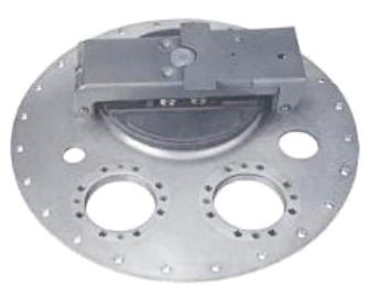 SIMEI FT-MH-140
560 mm pressed-plate tanker manhole cover with four accessory ports
Provides top access, automatic emergency pressure release and pressure/vacuum balancing for a fuel tanker; the illustrated accessory arrangement supports the specified tanker installation.
Technical details
560 mm pressed-plate tanker manhole cover with four accessory ports
Provides top access, automatic emergency pressure release and pressure/vacuum balancing for a fuel tanker; the illustrated accessory arrangement supports the specified tanker installation.
Technical detailsMain features
- Top-mounted access cover for tanks carrying gasoline, diesel, kerosene and other light fuels.
- An emergency exhaust mechanism automatically releases internal pressure when tank temperature or pressure rises.
- An internal pressure/vacuum vent admits or releases air to balance tank pressure.
- The secondary opening arrangement releases residual pressure before access; confirm the supplied latch configuration.
- Accessory openings can accommodate level sensing, vapour venting and dip-tube fittings where provided.
- The main plate is formed from steel sheet.
- Main-plate material and dimensions can be made to the required specification.
- The position and dimensions of the small plate can be customized.
- Four blanked accessory openings normally accept a vapour vent, optical sensor, dip tube and external pressure/vacuum vent.
Available Configurations
- Single or double pressure/vacuum vents as required.
- Four accessory openings with fittings selected for the tank system.
- Key, secondary opening device and emergency exhaust assembly are illustrated.
Technical & Ordering Data
| Nominal size | 560 mm nominal cover variant |
|---|---|
| Body / plate material | Pressed steel main plate; grade and small-plate material to be confirmed |
| Connection / operation | Top-mounted flanged cover; manual access opening with pressure-relief provisions |
| Emergency opening pressure | 21–35 kPa (catalogue family value; confirm setting for supplied assembly) |
| Maximum emergency airflow | 7,000 m³/h at 34 kPa (catalogue family value) |
| Temperature | −40 to +50 °C (catalogue family value) |
| Family nominal size reference | 20 in in the family table; individual variant dimensions are listed separately |
| Seal material | Confirm before quotation |
| Working pressure | Rated working pressure not stated; emergency opening pressure is a separate parameter |
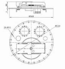
| Drawing outer diameter | Ø560 mm |
| Drawing diameter callout | Ø530 mm; confirm mounting function |
| Drawing holes | 24 × Ø11 mm |
| Drawing vertical callouts | Approximately 85 mm and 7 mm; confirm before manufacture |
Dimensions & Construction (1)
Drawings are selection references. Confirm dimensions, tolerances and interfaces against the approved drawing before manufacture.
Confirm Before Order
- Confirm seal compound and compatibility with the actual cargo.
- Confirm the emergency relief setting and flow rating for the supplied assembly.
- Confirm the drawing revision, mating tank opening and mounting arrangement; the family table gives 20 in across several variant sizes.
- Confirm which vents, sensor, dip tube, key, latch, hoop and base are included rather than optional.
- Elevation vertical callouts appear 85 and 7 mm but are low resolution.
Engineering Note
Values are transcribed from the supplied catalogue and are selection references, not a SIMEI test certificate or manufacturing approval. The photograph is the exact source model photograph; accessory illustrations may be shared where the same original detail recurs.
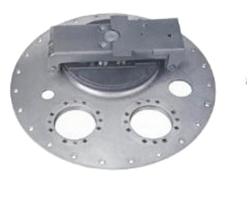 SIMEI FT-MH-150
580 mm pressed-plate tanker manhole cover with four accessory ports
Provides top access, automatic emergency pressure release and pressure/vacuum balancing for a fuel tanker; the illustrated accessory arrangement supports the specified tanker installation.
Technical details
580 mm pressed-plate tanker manhole cover with four accessory ports
Provides top access, automatic emergency pressure release and pressure/vacuum balancing for a fuel tanker; the illustrated accessory arrangement supports the specified tanker installation.
Technical detailsMain features
- Top-mounted access cover for tanks carrying gasoline, diesel, kerosene and other light fuels.
- An emergency exhaust mechanism automatically releases internal pressure when tank temperature or pressure rises.
- An internal pressure/vacuum vent admits or releases air to balance tank pressure.
- The secondary opening arrangement releases residual pressure before access; confirm the supplied latch configuration.
- Accessory openings can accommodate level sensing, vapour venting and dip-tube fittings where provided.
- The main plate is formed from steel sheet.
- Main-plate material and dimensions can be made to the required specification.
- The position and dimensions of the small plate can be customized.
- Four blanked accessory openings normally accept a vapour vent, optical sensor, dip tube and external pressure/vacuum vent.
Available Configurations
- Single or double pressure/vacuum vents as required.
- Four accessory openings with fittings selected for the tank system.
- Key, secondary opening device and emergency exhaust assembly are illustrated.
Technical & Ordering Data
| Nominal size | 580 mm nominal cover variant |
|---|---|
| Body / plate material | Pressed steel main plate; grade and small-plate material to be confirmed |
| Connection / operation | Top-mounted flanged cover; manual access opening with pressure-relief provisions |
| Emergency opening pressure | 21–35 kPa (catalogue family value; confirm setting for supplied assembly) |
| Maximum emergency airflow | 7,000 m³/h at 34 kPa (catalogue family value) |
| Temperature | −40 to +50 °C (catalogue family value) |
| Family nominal size reference | 20 in in the family table; individual variant dimensions are listed separately |
| Seal material | Confirm before quotation |
| Working pressure | Rated working pressure not stated; emergency opening pressure is a separate parameter |
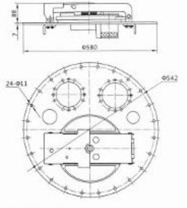
| Drawing outer diameter | Ø580 mm |
| Drawing diameter callout | Ø542 mm; confirm mounting function |
| Drawing holes | 24 × Ø11 mm |
| Drawing vertical callouts | Approximately 85 mm and 7 mm; confirm before manufacture |
Dimensions & Construction (1)
Drawings are selection references. Confirm dimensions, tolerances and interfaces against the approved drawing before manufacture.
Confirm Before Order
- Confirm seal compound and compatibility with the actual cargo.
- Confirm the emergency relief setting and flow rating for the supplied assembly.
- Confirm the drawing revision, mating tank opening and mounting arrangement; the family table gives 20 in across several variant sizes.
- Confirm which vents, sensor, dip tube, key, latch, hoop and base are included rather than optional.
- Elevation vertical callouts appear 85 and 7 mm but are low resolution.
Engineering Note
Values are transcribed from the supplied catalogue and are selection references, not a SIMEI test certificate or manufacturing approval. The photograph is the exact source model photograph; accessory illustrations may be shared where the same original detail recurs.
 SIMEI FT-MH-160
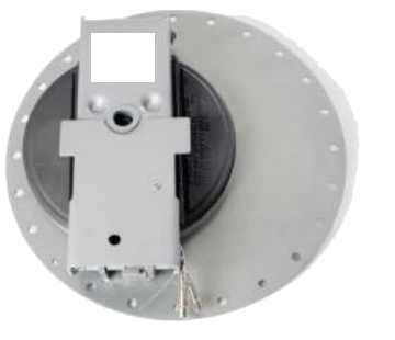
460 mm pressed-plate tanker manhole cover
Provides top access, automatic emergency pressure release and pressure/vacuum balancing for a fuel tanker; the illustrated accessory arrangement supports the specified tanker installation.
Technical details
460 mm pressed-plate tanker manhole cover
Provides top access, automatic emergency pressure release and pressure/vacuum balancing for a fuel tanker; the illustrated accessory arrangement supports the specified tanker installation.
Technical detailsMain features
- Top-mounted access cover for tanks carrying gasoline, diesel, kerosene and other light fuels.
- An emergency exhaust mechanism automatically releases internal pressure when tank temperature or pressure rises.
- An internal pressure/vacuum vent admits or releases air to balance tank pressure.
- The secondary opening arrangement releases residual pressure before access; confirm the supplied latch configuration.
- Accessory openings can accommodate level sensing, vapour venting and dip-tube fittings where provided.
- The main plate is formed from steel sheet.
- Main-plate material and dimensions can be made to the required specification.
- The position and dimensions of the small plate can be customized.
Available Configurations
- Single or double pressure/vacuum vents as required.
- Accessory-hole arrangement and small-plate position to order.
- Key, secondary opening device and emergency exhaust assembly are illustrated.
Technical & Ordering Data
| Nominal size | 460 mm nominal cover variant |
|---|---|
| Body / plate material | Pressed steel main plate; grade and small-plate material to be confirmed |
| Connection / operation | Top-mounted flanged cover; manual access opening with pressure-relief provisions |
| Emergency opening pressure | 21–35 kPa (catalogue family value; confirm setting for supplied assembly) |
| Maximum emergency airflow | 7,000 m³/h at 34 kPa (catalogue family value) |
| Temperature | −40 to +50 °C (catalogue family value) |
| Family nominal size reference | 20 in in the family table; individual variant dimensions are listed separately |
| Seal material | Confirm before quotation |
| Working pressure | Rated working pressure not stated; emergency opening pressure is a separate parameter |
Dimensions & Construction (1)
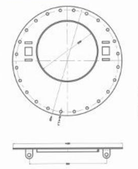
Drawings are selection references. Confirm dimensions, tolerances and interfaces against the approved drawing before manufacture.
Confirm Before Order
- Confirm seal compound and compatibility with the actual cargo.
- Confirm the emergency relief setting and flow rating for the supplied assembly.
- Confirm the drawing revision, mating tank opening and mounting arrangement; the family table gives 20 in across several variant sizes.
- Confirm which vents, sensor, dip tube, key, latch, hoop and base are included rather than optional.
- Numerical annotations in the plan and elevation are too blurred for reliable transcription.
- A printed supplier stamp on the photograph is excluded through an alpha-only mask; plate geometry is not reconstructed.
Engineering Note
Values are transcribed from the supplied catalogue and are selection references, not a SIMEI test certificate or manufacturing approval. The photograph is the exact source model photograph; accessory illustrations may be shared where the same original detail recurs. A supplier marking is removed with a transparent mask; no replacement surface is synthesized.
 SIMEI FT-MH-170
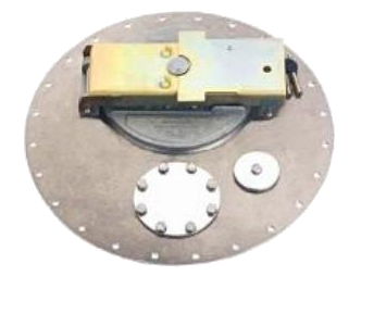
560 mm pressed-plate tanker manhole cover with two accessory ports
Provides top access, automatic emergency pressure release and pressure/vacuum balancing for a fuel tanker; the illustrated accessory arrangement supports the specified tanker installation.
Technical details
560 mm pressed-plate tanker manhole cover with two accessory ports
Provides top access, automatic emergency pressure release and pressure/vacuum balancing for a fuel tanker; the illustrated accessory arrangement supports the specified tanker installation.
Technical detailsMain features
- Top-mounted access cover for tanks carrying gasoline, diesel, kerosene and other light fuels.
- An emergency exhaust mechanism automatically releases internal pressure when tank temperature or pressure rises.
- An internal pressure/vacuum vent admits or releases air to balance tank pressure.
- The secondary opening arrangement releases residual pressure before access; confirm the supplied latch configuration.
- Accessory openings can accommodate level sensing, vapour venting and dip-tube fittings where provided.
- The main plate is formed from steel sheet.
- Main-plate material and dimensions can be made to the required specification.
- The position and dimensions of the small plate can be customized.
- Two blanked accessory openings normally accept a vapour adaptor valve and optical sensor.
Available Configurations
- Single or double pressure/vacuum vents as required.
- Vapour adaptor valve and optical sensor at the two accessory openings.
- Key, secondary opening device and emergency exhaust assembly are illustrated.
Technical & Ordering Data
| Nominal size | 560 mm nominal cover variant |
|---|---|
| Body / plate material | Pressed steel main plate; grade and small-plate material to be confirmed |
| Connection / operation | Top-mounted flanged cover; manual access opening with pressure-relief provisions |
| Emergency opening pressure | 21–35 kPa (catalogue family value; confirm setting for supplied assembly) |
| Maximum emergency airflow | 7,000 m³/h at 34 kPa (catalogue family value) |
| Temperature | −40 to +50 °C (catalogue family value) |
| Family nominal size reference | 20 in in the family table; individual variant dimensions are listed separately |
| Seal material | Confirm before quotation |
| Working pressure | Rated working pressure not stated; emergency opening pressure is a separate parameter |
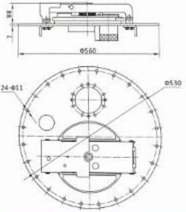
| Drawing outer diameter | Ø560 mm |
| Drawing diameter callout | Ø530 mm; confirm mounting function |
| Drawing holes | 24 × Ø11 mm |
| Drawing plate callout | 7 mm; confirm before manufacture |
Dimensions & Construction (1)
Drawings are selection references. Confirm dimensions, tolerances and interfaces against the approved drawing before manufacture.
Confirm Before Order
- Confirm seal compound and compatibility with the actual cargo.
- Confirm the emergency relief setting and flow rating for the supplied assembly.
- Confirm the drawing revision, mating tank opening and mounting arrangement; the family table gives 20 in across several variant sizes.
- Confirm which vents, sensor, dip tube, key, latch, hoop and base are included rather than optional.
- The upper vertical dimension in the elevation is blurred and is not transcribed.
Engineering Note
Values are transcribed from the supplied catalogue and are selection references, not a SIMEI test certificate or manufacturing approval. The photograph is the exact source model photograph; accessory illustrations may be shared where the same original detail recurs.
 SIMEI FT-MH-180
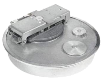
500 mm hooped tanker manhole cover with small access plate
Provides top access, automatic emergency pressure release and pressure/vacuum balancing for a fuel tanker; the illustrated accessory arrangement supports the specified tanker installation.
Technical details
500 mm hooped tanker manhole cover with small access plate
Provides top access, automatic emergency pressure release and pressure/vacuum balancing for a fuel tanker; the illustrated accessory arrangement supports the specified tanker installation.
Technical detailsMain features
- Top-mounted access cover for tanks carrying gasoline, diesel, kerosene and other light fuels.
- An emergency exhaust mechanism automatically releases internal pressure when tank temperature or pressure rises.
- An internal pressure/vacuum vent admits or releases air to balance tank pressure.
- The secondary opening arrangement releases residual pressure before access; confirm the supplied latch configuration.
- Accessory openings can accommodate level sensing, vapour venting and dip-tube fittings where provided.
- The main plate is pressed from steel sheet; plate material and the number of blanked accessory openings are configurable.
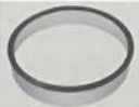
- The base is formed by rolling and pressure welding sheet material.
- Base material and height can be specified for the tank.
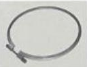
- A clamping hoop provides the installation connection.
Available Configurations
- Single or double pressure/vacuum vents as required.
- Accessory-opening quantity, main-plate material, base material and base height to order.
- Hoop and base ring are illustrated.
Technical & Ordering Data
| Nominal size | 500 mm nominal cover variant |
|---|---|
| Body / plate material | Pressed steel main plate; base material selectable |
| Connection / operation | Hooped installation |
| Emergency opening pressure | 21–35 kPa (catalogue family value; confirm setting for supplied assembly) |
| Maximum emergency airflow | 7,000 m³/h at 34 kPa (catalogue family value) |
| Temperature | −40 to +50 °C (catalogue family value) |
| Family nominal size reference | 20 in in the family table; individual variant dimensions are listed separately |
| Seal material | Confirm before quotation |
| Working pressure | Rated working pressure not stated; emergency opening pressure is a separate parameter |
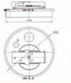
| Drawing base diameter | Ø515 mm |
| Drawing cover diameter callout | Ø550 mm |
Dimensions & Construction (1)
Drawings are selection references. Confirm dimensions, tolerances and interfaces against the approved drawing before manufacture.
Confirm Before Order
- Confirm seal compound and compatibility with the actual cargo.
- Confirm the emergency relief setting and flow rating for the supplied assembly.
- Confirm the drawing revision, mating tank opening and mounting arrangement; the family table gives 20 in across several variant sizes.
- Confirm which vents, sensor, dip tube, key, latch, hoop and base are included rather than optional.
- Source option captions for the latch, hoop and base images are shifted; image content is used for neutral captions.
Engineering Note
Values are transcribed from the supplied catalogue and are selection references, not a SIMEI test certificate or manufacturing approval. The photograph is the exact source model photograph; accessory illustrations may be shared where the same original detail recurs.
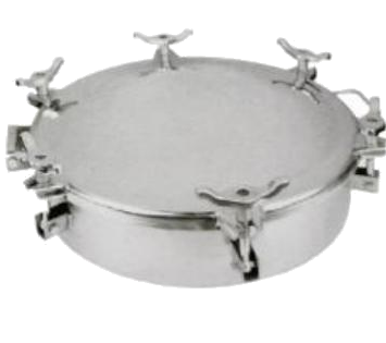 SIMEI FT-MH-190
500 mm hooped tanker manhole cover with clamped full cover
Provides top access, automatic emergency pressure release and pressure/vacuum balancing for a fuel tanker; the illustrated accessory arrangement supports the specified tanker installation.
Technical details
500 mm hooped tanker manhole cover with clamped full cover
Provides top access, automatic emergency pressure release and pressure/vacuum balancing for a fuel tanker; the illustrated accessory arrangement supports the specified tanker installation.
Technical detailsMain features
- Top-mounted access cover for tanks carrying gasoline, diesel, kerosene and other light fuels.
- An emergency exhaust mechanism automatically releases internal pressure when tank temperature or pressure rises.
- An internal pressure/vacuum vent admits or releases air to balance tank pressure.
- The secondary opening arrangement releases residual pressure before access; confirm the supplied latch configuration.
- Accessory openings can accommodate level sensing, vapour venting and dip-tube fittings where provided.
- The main plate is pressed from carbon steel; plate material, dimensions and number of blanked accessory openings are configurable.
- The base is formed by rolling and pressure welding sheet material.
- Base material and height can be specified for the tank.
- A clamping hoop provides the installation connection.
- A dedicated pressure/vacuum vent structure and secondary opening device are illustrated.
Available Configurations
- Dedicated pressure/vacuum vent configuration shown in the original photograph.
- Secondary opening device, clamping hoop and base ring.
- Main-plate material, accessory openings, base material and base height to order.
Technical & Ordering Data
| Nominal size | 500 mm nominal cover variant |
|---|---|
| Body / plate material | Pressed carbon steel main plate; base material selectable |
| Connection / operation | Hooped installation |
| Emergency opening pressure | 21–35 kPa (catalogue family value; confirm setting for supplied assembly) |
| Maximum emergency airflow | 7,000 m³/h at 34 kPa (catalogue family value) |
| Temperature | −40 to +50 °C (catalogue family value) |
| Family nominal size reference | 20 in in the family table; individual variant dimensions are listed separately |
| Seal material | Confirm before quotation |
| Working pressure | Rated working pressure not stated; emergency opening pressure is a separate parameter |
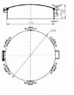
| Drawing base diameter | Approximately Ø510 mm; verify before ordering |
| Drawing cover diameter callout | Approximately Ø550 mm; verify before ordering |
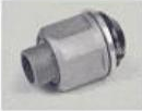
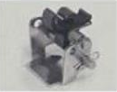
Dimensions & Construction (1)
Drawings are selection references. Confirm dimensions, tolerances and interfaces against the approved drawing before manufacture.
Confirm Before Order
- Confirm seal compound and compatibility with the actual cargo.
- Confirm the emergency relief setting and flow rating for the supplied assembly.
- Confirm the drawing revision, mating tank opening and mounting arrangement; the family table gives 20 in across several variant sizes.
- Confirm which vents, sensor, dip tube, key, latch, hoop and base are included rather than optional.
- The nominal product suffix is 500, while the drawing appears to show Ø510 and Ø550 mm.
- Three small elevation callouts at the right are not reliably legible.
- The illustrated dedicated vent has no separately mapped inventory code; confirm its specification with the cover.
Engineering Note
Values are transcribed from the supplied catalogue and are selection references, not a SIMEI test certificate or manufacturing approval. The photograph is the exact source model photograph; accessory illustrations may be shared where the same original detail recurs.
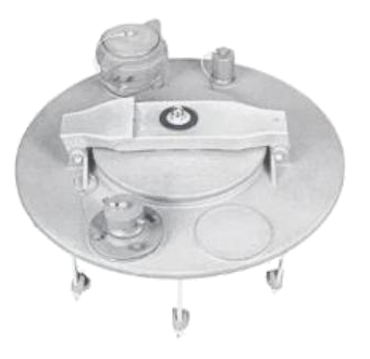 SIMEI FT-MH-200
500 mm interlocked hook-type tanker manhole cover
Provides top access, automatic emergency pressure release and pressure/vacuum balancing for a fuel tanker; the illustrated accessory arrangement supports the specified tanker installation.
Technical details
500 mm interlocked hook-type tanker manhole cover
Provides top access, automatic emergency pressure release and pressure/vacuum balancing for a fuel tanker; the illustrated accessory arrangement supports the specified tanker installation.
Technical detailsMain features
- Top-mounted access cover for tanks carrying gasoline, diesel, kerosene and other light fuels.
- An emergency exhaust mechanism automatically releases internal pressure when tank temperature or pressure rises.
- An internal pressure/vacuum vent admits or releases air to balance tank pressure.
- The secondary opening arrangement releases residual pressure before access; confirm the supplied latch configuration.
- Accessory openings can accommodate level sensing, vapour venting and dip-tube fittings where provided.
- The main plate and small plate are forged and receive oxidation surface treatment.
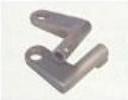
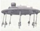
- The hook installation is interlocked: the main cover cannot be opened until the small plate has been opened.
- Three blanked accessory openings accept a dip tube and flanged vapour adaptor; optical sensor or external pressure/vacuum vent arrangements are also described.
Available Configurations
- Hook installation with retained studs.
- Key and emergency exhaust assembly are illustrated.
- Dip tube, flanged vapour adaptor, optical sensor or external pressure/vacuum vent according to the required port arrangement.
Technical & Ordering Data
| Nominal size | 500 mm nominal cover variant |
|---|---|
| Body / plate material | Forged main and small plates according to the product text; alloy/grade to confirm |
| Connection / operation | Interlocked hook-type installation |
| Emergency opening pressure | 21–35 kPa (catalogue family value; confirm setting for supplied assembly) |
| Maximum emergency airflow | 7,000 m³/h at 34 kPa (catalogue family value) |
| Temperature | −40 to +50 °C (catalogue family value) |
| Family nominal size reference | 20 in in the family table; individual variant dimensions are listed separately |
| Seal material | Confirm before quotation |
| Working pressure | Rated working pressure not stated; emergency opening pressure is a separate parameter |
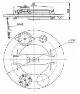
| Drawing diameter callout | Ø530 mm |
| Drawing height | 145 mm |
| Drawing fastener callout | 8 × M8 |

Dimensions & Construction (1)
Drawings are selection references. Confirm dimensions, tolerances and interfaces against the approved drawing before manufacture.
Confirm Before Order
- Confirm seal compound and compatibility with the actual cargo.
- Confirm the emergency relief setting and flow rating for the supplied assembly.
- Confirm the drawing revision, mating tank opening and mounting arrangement; the family table gives 20 in across several variant sizes.
- Confirm which vents, sensor, dip tube, key, latch, hoop and base are included rather than optional.
- The family table says aluminium alloy/carbon steel; the exact forged material grade is not supplied.
Engineering Note
Values are transcribed from the supplied catalogue and are selection references, not a SIMEI test certificate or manufacturing approval. The photograph is the exact source model photograph; accessory illustrations may be shared where the same original detail recurs.
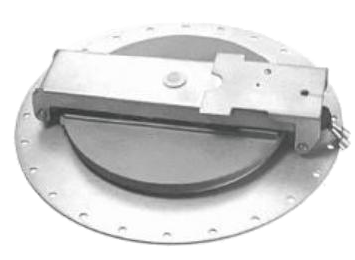 SIMEI FT-MH-210
560 mm tanker manhole cover with 13-inch small access plate
Provides top access, automatic emergency pressure release and pressure/vacuum balancing for a fuel tanker; the illustrated accessory arrangement supports the specified tanker installation.
Technical details
560 mm tanker manhole cover with 13-inch small access plate
Provides top access, automatic emergency pressure release and pressure/vacuum balancing for a fuel tanker; the illustrated accessory arrangement supports the specified tanker installation.
Technical detailsMain features
- Top-mounted access cover for tanks carrying gasoline, diesel, kerosene and other light fuels.
- An emergency exhaust mechanism automatically releases internal pressure when tank temperature or pressure rises.
- An internal pressure/vacuum vent admits or releases air to balance tank pressure.
- The secondary opening arrangement releases residual pressure before access; confirm the supplied latch configuration.
- Accessory openings can accommodate level sensing, vapour venting and dip-tube fittings where provided.
- The main plate is pressed from carbon steel; plate material and dimensions can be specified.
- The described standard main plate has no blanked accessory openings.
- The small plate is described as 13 in nominal diameter for faster, more convenient oil loading.
Available Configurations
- Single or double pressure/vacuum vents as required.
- Key, secondary opening device and emergency exhaust assembly are illustrated.
- Main-plate material and dimensions to order.
Technical & Ordering Data
| Nominal size | 560 mm nominal cover; 13 in small-plate nominal opening stated in text |
|---|---|
| Body / plate material | Pressed carbon steel main plate stated in the product text; final grade to confirm |
| Connection / operation | Top-mounted flanged cover; manual access opening with pressure-relief provisions |
| Emergency opening pressure | 21–35 kPa (catalogue family value; confirm setting for supplied assembly) |
| Maximum emergency airflow | 7,000 m³/h at 34 kPa (catalogue family value) |
| Temperature | −40 to +50 °C (catalogue family value) |
| Family nominal size reference | 20 in in the family table; individual variant dimensions are listed separately |
| Seal material | Confirm before quotation |
| Working pressure | Rated working pressure not stated; emergency opening pressure is a separate parameter |
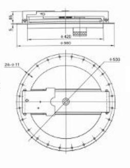
| Drawing outer diameter | Ø560 mm |
| Drawing internal diameter callout | Ø420 mm; do not equate this callout to the text’s 13 in opening |
| Drawing diameter callout | Ø530 mm; confirm mounting function |
| Drawing holes | 24 × Ø11 mm |
| Drawing vertical callouts | Approximately 85 mm and 5 mm; verify before manufacture |
Dimensions & Construction (1)
Drawings are selection references. Confirm dimensions, tolerances and interfaces against the approved drawing before manufacture.
Confirm Before Order
- Confirm seal compound and compatibility with the actual cargo.
- Confirm the emergency relief setting and flow rating for the supplied assembly.
- Confirm the drawing revision, mating tank opening and mounting arrangement; the family table gives 20 in across several variant sizes.
- Confirm which vents, sensor, dip tube, key, latch, hoop and base are included rather than optional.
- The first feature mentions configurable blanking-hole quantity, while a later feature says there are no blanked holes. The standard illustrated version is described as having none.
- The source text specifies a 13 in small plate, but the drawing also shows Ø420 mm; confirm the clear access opening.
- Vertical drawing callouts are low resolution.
Engineering Note
Values are transcribed from the supplied catalogue and are selection references, not a SIMEI test certificate or manufacturing approval. The photograph is the exact source model photograph; accessory illustrations may be shared where the same original detail recurs.
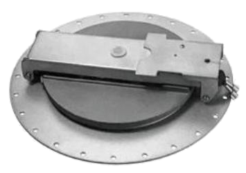 SIMEI FT-MH-220
580 mm tanker manhole cover with 13-inch small access plate
Provides top access, automatic emergency pressure release and pressure/vacuum balancing for a fuel tanker; the illustrated accessory arrangement supports the specified tanker installation.
Technical details
580 mm tanker manhole cover with 13-inch small access plate
Provides top access, automatic emergency pressure release and pressure/vacuum balancing for a fuel tanker; the illustrated accessory arrangement supports the specified tanker installation.
Technical detailsMain features
- Top-mounted access cover for tanks carrying gasoline, diesel, kerosene and other light fuels.
- An emergency exhaust mechanism automatically releases internal pressure when tank temperature or pressure rises.
- An internal pressure/vacuum vent admits or releases air to balance tank pressure.
- The secondary opening arrangement releases residual pressure before access; confirm the supplied latch configuration.
- Accessory openings can accommodate level sensing, vapour venting and dip-tube fittings where provided.
- Main-plate material can be aluminium or carbon steel.
- The main plate has no blanked accessory openings.
- The small plate is described as 13 in nominal diameter for faster, more convenient oil loading.
Available Configurations
- Aluminium or carbon steel main plate.
- Single or double pressure/vacuum vents as required.
- Key, secondary opening device and emergency exhaust assembly are illustrated.
Technical & Ordering Data
| Nominal size | 580 mm nominal cover; 13 in small-plate nominal opening stated in text |
|---|---|
| Body / plate material | Aluminium or carbon steel main plate option |
| Connection / operation | Top-mounted flanged cover; manual access opening with pressure-relief provisions |
| Emergency opening pressure | 21–35 kPa (catalogue family value; confirm setting for supplied assembly) |
| Maximum emergency airflow | 7,000 m³/h at 34 kPa (catalogue family value) |
| Temperature | −40 to +50 °C (catalogue family value) |
| Family nominal size reference | 20 in in the family table; individual variant dimensions are listed separately |
| Seal material | Confirm before quotation |
| Working pressure | Rated working pressure not stated; emergency opening pressure is a separate parameter |
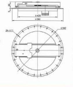
| Drawing outer diameter | Ø580 mm |
| Drawing internal diameter callout | Ø420 mm; do not equate this callout to the text’s 13 in opening |
| Drawing diameter callout | Ø542 mm; confirm mounting function |
| Drawing holes | 24 × Ø11 mm |
| Drawing vertical callouts | Approximately 85 mm and 5 mm; verify before manufacture |
Dimensions & Construction (1)
Drawings are selection references. Confirm dimensions, tolerances and interfaces against the approved drawing before manufacture.
Confirm Before Order
- Confirm seal compound and compatibility with the actual cargo.
- Confirm the emergency relief setting and flow rating for the supplied assembly.
- Confirm the drawing revision, mating tank opening and mounting arrangement; the family table gives 20 in across several variant sizes.
- Confirm which vents, sensor, dip tube, key, latch, hoop and base are included rather than optional.
- The source text specifies a 13 in small plate, but the drawing also shows Ø420 mm; confirm the clear access opening.
- Vertical drawing callouts are low resolution.
Engineering Note
Values are transcribed from the supplied catalogue and are selection references, not a SIMEI test certificate or manufacturing approval. The photograph is the exact source model photograph; accessory illustrations may be shared where the same original detail recurs.
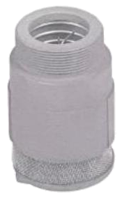 SIMEI FT-PV-100
Threaded pressure/vacuum vent with M59 × 2 connection
Balances internal and external tanker pressure by admitting or discharging air through a top-mounted pressure/vacuum vent.
Technical details
Threaded pressure/vacuum vent with M59 × 2 connection
Balances internal and external tanker pressure by admitting or discharging air through a top-mounted pressure/vacuum vent.
Technical detailsMain features
- Automatic inlet and outlet action responds to tank pressure difference.
- The rollover mechanism is intended to close at a specified inclination to prevent fuel spilling; the source gives no activation angle.
- A precision spring controls the vent action.
- The valve body is cast from aluminium alloy and its surface is passivated.
Available Configurations
- Choose the illustrated threaded or flanged connection to suit the manhole or tank connection.
- Confirm the required pressure and vacuum opening settings before ordering.
Technical & Ordering Data
| Nominal size | Connection dimensions are given below; no separate nominal bore is stated |
|---|---|
| Body material | Cast, passivated aluminium alloy |
| Seal material | Confirm before quotation |
| Outlet opening pressure | +6 to +12 kPa (family value) |
| Inlet opening pressure | −2 to −4 kPa (family value) |
| Flow rate | 600 L/min (family value; test conditions not specified) |
| Working pressure | Rated working pressure is not specified separately from opening pressures |
| Temperature | Confirm before quotation: the source table prints −20 to +500 °C; the upper limit appears erroneous and must not be used as a rating |
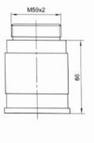
| Connection | M59 × 2 thread |
| Drawing body-height callout | Appears to be 86 mm; source is blurred and this is not an overall-height specification |
Dimensions & Construction (1)
Drawings are selection references. Confirm dimensions, tolerances and interfaces against the approved drawing before manufacture.
Confirm Before Order
- Confirm seal compound, cargo compatibility, spring material and opening-pressure settings.
- Confirm rated temperature: the printed +500 °C upper limit is an apparent source error.
- Confirm rollover closing angle and tested leakage performance; the source gives a generic closure statement only.
- Confirm flow test conditions and connection drawing.
- Height callout appears 86 mm after rotating the native scan; prior inventory read 98 mm. Must be confirmed.
Engineering Note
Values are transcribed from the supplied catalogue and are selection references, not a SIMEI test certificate or manufacturing approval. Family data on printed page 04 applies to the pressure/vacuum vent group; it does not define a separately certified rating for each illustrated model.
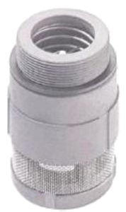 SIMEI FT-PV-110
Extended threaded pressure/vacuum vent with M59 × 2 connection
Balances internal and external tanker pressure by admitting or discharging air through a top-mounted pressure/vacuum vent.
Technical details
Extended threaded pressure/vacuum vent with M59 × 2 connection
Balances internal and external tanker pressure by admitting or discharging air through a top-mounted pressure/vacuum vent.
Technical detailsMain features
- Automatic inlet and outlet action responds to tank pressure difference.
- The rollover mechanism is intended to close at a specified inclination to prevent fuel spilling; the source gives no activation angle.
- A precision spring controls the vent action.
- The valve body is cast from aluminium alloy and its surface is passivated.
Available Configurations
- Choose the illustrated threaded or flanged connection to suit the manhole or tank connection.
- Confirm the required pressure and vacuum opening settings before ordering.
Technical & Ordering Data
| Nominal size | Connection dimensions are given below; no separate nominal bore is stated |
|---|---|
| Body material | Cast, passivated aluminium alloy |
| Seal material | Confirm before quotation |
| Outlet opening pressure | +6 to +12 kPa (family value) |
| Inlet opening pressure | −2 to −4 kPa (family value) |
| Flow rate | 600 L/min (family value; test conditions not specified) |
| Working pressure | Rated working pressure is not specified separately from opening pressures |
| Temperature | Confirm before quotation: the source table prints −20 to +500 °C; the upper limit appears erroneous and must not be used as a rating |
| Connection | M59 × 2 thread |
| Drawing height | 120 mm |
Dimensions & Construction (1)
Drawings are selection references. Confirm dimensions, tolerances and interfaces against the approved drawing before manufacture.
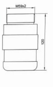
Confirm Before Order
- Confirm seal compound, cargo compatibility, spring material and opening-pressure settings.
- Confirm rated temperature: the printed +500 °C upper limit is an apparent source error.
- Confirm rollover closing angle and tested leakage performance; the source gives a generic closure statement only.
- Confirm flow test conditions and connection drawing.
Engineering Note
Values are transcribed from the supplied catalogue and are selection references, not a SIMEI test certificate or manufacturing approval. Family data on printed page 04 applies to the pressure/vacuum vent group; it does not define a separately certified rating for each illustrated model.
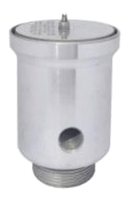 SIMEI FT-PV-120
Threaded pressure/vacuum vent with sectioned body reference
Balances internal and external tanker pressure by admitting or discharging air through a top-mounted pressure/vacuum vent.
Technical details
Threaded pressure/vacuum vent with sectioned body reference
Balances internal and external tanker pressure by admitting or discharging air through a top-mounted pressure/vacuum vent.
Technical detailsMain features
- Automatic inlet and outlet action responds to tank pressure difference.
- The rollover mechanism is intended to close at a specified inclination to prevent fuel spilling; the source gives no activation angle.
- A precision spring controls the vent action.
- The valve body is cast from aluminium alloy and its surface is passivated.
Available Configurations
- Choose the illustrated threaded or flanged connection to suit the manhole or tank connection.
- Confirm the required pressure and vacuum opening settings before ordering.
Technical & Ordering Data
| Nominal size | Connection dimensions are given below; no separate nominal bore is stated |
|---|---|
| Body material | Cast, passivated aluminium alloy |
| Seal material | Confirm before quotation |
| Outlet opening pressure | +6 to +12 kPa (family value) |
| Inlet opening pressure | −2 to −4 kPa (family value) |
| Flow rate | 600 L/min (family value; test conditions not specified) |
| Working pressure | Rated working pressure is not specified separately from opening pressures |
| Temperature | Confirm before quotation: the source table prints −20 to +500 °C; the upper limit appears erroneous and must not be used as a rating |
| Connection | Drawing appears to read NPSC 1½ in; confirm thread standard and size |
| Drawing top diameter | Ø67.5 mm |
| Drawing height | 93.5 mm |
Dimensions & Construction (1)
Drawings are selection references. Confirm dimensions, tolerances and interfaces against the approved drawing before manufacture.
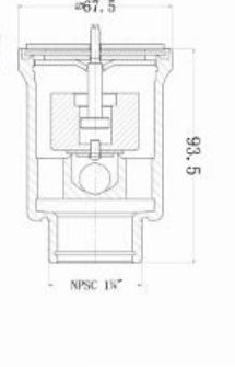
Confirm Before Order
- Confirm seal compound, cargo compatibility, spring material and opening-pressure settings.
- Confirm rated temperature: the printed +500 °C upper limit is an apparent source error.
- Confirm rollover closing angle and tested leakage performance; the source gives a generic closure statement only.
- Confirm flow test conditions and connection drawing.
- The small lower thread label appears NPSC 1½ in and requires confirmation before quotation.
Engineering Note
Values are transcribed from the supplied catalogue and are selection references, not a SIMEI test certificate or manufacturing approval. Family data on printed page 04 applies to the pressure/vacuum vent group; it does not define a separately certified rating for each illustrated model.
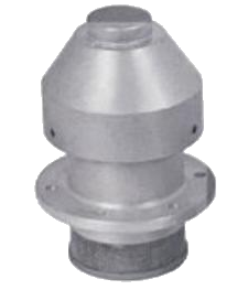 SIMEI FT-PV-130
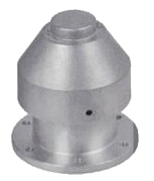
Flanged pressure/vacuum vent, 110 mm flange
Balances internal and external tanker pressure by admitting or discharging air through a top-mounted pressure/vacuum vent.
Technical details
Flanged pressure/vacuum vent, 110 mm flange
Balances internal and external tanker pressure by admitting or discharging air through a top-mounted pressure/vacuum vent.
Technical detailsMain features
- Automatic inlet and outlet action responds to tank pressure difference.
- The rollover mechanism is intended to close at a specified inclination to prevent fuel spilling; the source gives no activation angle.
- A precision spring controls the vent action.
- The valve body is cast from aluminium alloy and its surface is passivated.
Available Configurations
- Choose the illustrated threaded or flanged connection to suit the manhole or tank connection.
- Confirm the required pressure and vacuum opening settings before ordering.
Technical & Ordering Data
| Nominal size | Connection dimensions are given below; no separate nominal bore is stated |
|---|---|
| Body material | Cast, passivated aluminium alloy |
| Seal material | Confirm before quotation |
| Outlet opening pressure | +6 to +12 kPa (family value) |
| Inlet opening pressure | −2 to −4 kPa (family value) |
| Flow rate | 600 L/min (family value; test conditions not specified) |
| Working pressure | Rated working pressure is not specified separately from opening pressures |
| Temperature | Confirm before quotation: the source table prints −20 to +500 °C; the upper limit appears erroneous and must not be used as a rating |
| Connection | Flanged |
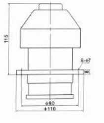
| Drawing flange outer diameter | Ø110 mm |
| Drawing secondary diameter | Ø90 mm; the supplied elevation does not establish whether this is a register or bolt-circle diameter |
| Drawing holes | 6 × Ø7 mm |
| Drawing height above the indicated flange reference | 115 mm |
| Drawing flange thickness | 8 mm |
Dimensions & Construction (1)
Drawings are selection references. Confirm dimensions, tolerances and interfaces against the approved drawing before manufacture.
Confirm Before Order
- Confirm seal compound, cargo compatibility, spring material and opening-pressure settings.
- Confirm rated temperature: the printed +500 °C upper limit is an apparent source error.
- Confirm rollover closing angle and tested leakage performance; the source gives a generic closure statement only.
- Confirm flow test conditions and connection drawing.
Engineering Note
Values are transcribed from the supplied catalogue and are selection references, not a SIMEI test certificate or manufacturing approval. Family data on printed page 04 applies to the pressure/vacuum vent group; it does not define a separately certified rating for each illustrated model.
 SIMEI FT-PV-140
Flanged pressure/vacuum vent, 107 mm flange
Balances internal and external tanker pressure by admitting or discharging air through a top-mounted pressure/vacuum vent.
Technical details
Flanged pressure/vacuum vent, 107 mm flange
Balances internal and external tanker pressure by admitting or discharging air through a top-mounted pressure/vacuum vent.
Technical detailsMain features
- Automatic inlet and outlet action responds to tank pressure difference.
- The rollover mechanism is intended to close at a specified inclination to prevent fuel spilling; the source gives no activation angle.
- A precision spring controls the vent action.
- The valve body is cast from aluminium alloy and its surface is passivated.
Available Configurations
- Choose the illustrated threaded or flanged connection to suit the manhole or tank connection.
- Confirm the required pressure and vacuum opening settings before ordering.
Technical & Ordering Data
| Nominal size | Connection dimensions are given below; no separate nominal bore is stated |
|---|---|
| Body material | Cast, passivated aluminium alloy |
| Seal material | Confirm before quotation |
| Outlet opening pressure | +6 to +12 kPa (family value) |
| Inlet opening pressure | −2 to −4 kPa (family value) |
| Flow rate | 600 L/min (family value; test conditions not specified) |
| Working pressure | Rated working pressure is not specified separately from opening pressures |
| Temperature | Confirm before quotation: the source table prints −20 to +500 °C; the upper limit appears erroneous and must not be used as a rating |
| Connection | Flanged |
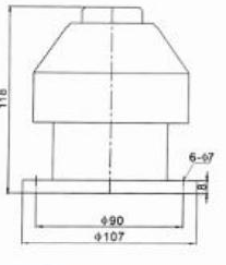
| Drawing flange outer diameter | Ø107 mm |
| Drawing secondary diameter | Ø90 mm; the supplied elevation does not establish whether this is a register or bolt-circle diameter |
| Drawing holes | 6 × Ø7 mm |
| Drawing height to flange reference | 118 mm |
| Drawing flange thickness | 8 mm |
Dimensions & Construction (1)
Drawings are selection references. Confirm dimensions, tolerances and interfaces against the approved drawing before manufacture.
Confirm Before Order
- Confirm seal compound, cargo compatibility, spring material and opening-pressure settings.
- Confirm rated temperature: the printed +500 °C upper limit is an apparent source error.
- Confirm rollover closing angle and tested leakage performance; the source gives a generic closure statement only.
- Confirm flow test conditions and connection drawing.
Engineering Note
Values are transcribed from the supplied catalogue and are selection references, not a SIMEI test certificate or manufacturing approval. Family data on printed page 04 applies to the pressure/vacuum vent group; it does not define a separately certified rating for each illustrated model.
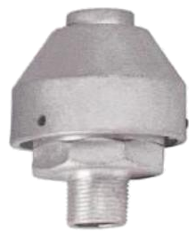
 SIMEI FT-PV-150
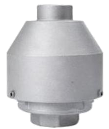
Compact threaded pressure/vacuum vent
Balances internal and external tanker pressure by admitting or discharging air through a top-mounted pressure/vacuum vent.
Technical details
Compact threaded pressure/vacuum vent
Balances internal and external tanker pressure by admitting or discharging air through a top-mounted pressure/vacuum vent.
Technical detailsMain features
- Automatic inlet and outlet action responds to tank pressure difference.
- The rollover mechanism is intended to close at a specified inclination to prevent fuel spilling; the source gives no activation angle.
- A precision spring controls the vent action.
- The valve body is cast from aluminium alloy and its surface is passivated.
Available Configurations
- Choose the illustrated threaded or flanged connection to suit the manhole or tank connection.
- Confirm the required pressure and vacuum opening settings before ordering.
Technical & Ordering Data
| Nominal size | Connection dimensions are given below; no separate nominal bore is stated |
|---|---|
| Body material | Cast, passivated aluminium alloy |
| Seal material | Confirm before quotation |
| Outlet opening pressure | +6 to +12 kPa (family value) |
| Inlet opening pressure | −2 to −4 kPa (family value) |
| Flow rate | 600 L/min (family value; test conditions not specified) |
| Working pressure | Rated working pressure is not specified separately from opening pressures |
| Temperature | Confirm before quotation: the source table prints −20 to +500 °C; the upper limit appears erroneous and must not be used as a rating |
| Connection | Threaded; thread designation is not specified |
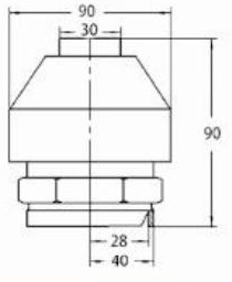
| Drawing body width | 90 mm |
| Drawing top neck width | 30 mm |
| Drawing height | 90 mm |
| Drawing lower connection callouts | 28 mm and 40 mm; the drawing does not identify a thread standard |
Dimensions & Construction (1)
Drawings are selection references. Confirm dimensions, tolerances and interfaces against the approved drawing before manufacture.
Confirm Before Order
- Confirm seal compound, cargo compatibility, spring material and opening-pressure settings.
- Confirm rated temperature: the printed +500 °C upper limit is an apparent source error.
- Confirm rollover closing angle and tested leakage performance; the source gives a generic closure statement only.
- Confirm flow test conditions and connection drawing.
- Lower 28/40 mm callouts must not be interpreted as a thread specification.
Engineering Note
Values are transcribed from the supplied catalogue and are selection references, not a SIMEI test certificate or manufacturing approval. Family data on printed page 04 applies to the pressure/vacuum vent group; it does not define a separately certified rating for each illustrated model.
 SIMEI FT-PV-160
Threaded pressure/vacuum vent with G1 connection
Balances internal and external tanker pressure by admitting or discharging air through a top-mounted pressure/vacuum vent.
Technical details
Threaded pressure/vacuum vent with G1 connection
Balances internal and external tanker pressure by admitting or discharging air through a top-mounted pressure/vacuum vent.
Technical detailsMain features
- Automatic inlet and outlet action responds to tank pressure difference.
- The rollover mechanism is intended to close at a specified inclination to prevent fuel spilling; the source gives no activation angle.
- A precision spring controls the vent action.
- The valve body is cast from aluminium alloy and its surface is passivated.
Available Configurations
- Choose the illustrated threaded or flanged connection to suit the manhole or tank connection.
- Confirm the required pressure and vacuum opening settings before ordering.
Technical & Ordering Data
| Nominal size | Connection dimensions are given below; no separate nominal bore is stated |
|---|---|
| Body material | Cast, passivated aluminium alloy |
| Seal material | Confirm before quotation |
| Outlet opening pressure | +6 to +12 kPa (family value) |
| Inlet opening pressure | −2 to −4 kPa (family value) |
| Flow rate | 600 L/min (family value; test conditions not specified) |
| Working pressure | Rated working pressure is not specified separately from opening pressures |
| Temperature | Confirm before quotation: the source table prints −20 to +500 °C; the upper limit appears erroneous and must not be used as a rating |
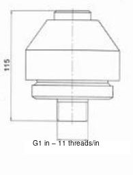
| Connection | Source drawing prints G1 in–11 threads/in; confirm compatibility |
| Drawing height to lower body reference | 115 mm |
Dimensions & Construction (1)
Drawings are selection references. Confirm dimensions, tolerances and interfaces against the approved drawing before manufacture.
Confirm Before Order
- Confirm seal compound, cargo compatibility, spring material and opening-pressure settings.
- Confirm rated temperature: the printed +500 °C upper limit is an apparent source error.
- Confirm rollover closing angle and tested leakage performance; the source gives a generic closure statement only.
- Confirm flow test conditions and connection drawing.
- G1 in–11 threads/in is transcribed as printed; the thread should be verified against a current manufacturing drawing.
Engineering Note
Values are transcribed from the supplied catalogue and are selection references, not a SIMEI test certificate or manufacturing approval. Family data on printed page 04 applies to the pressure/vacuum vent group; it does not define a separately certified rating for each illustrated model.
SIMEI ENERGY
Selection and ordering
Send the SIMEI code, quantity, transported medium, operating conditions and mating drawing. Confirm materials, seals, interfaces and operating requirements before ordering.